Push pull class amplifier designs choosing Transformer topology microcontrollerslab Push pull amplifier, working and theory. class a , class b , class ab
DC to DC converter using push pull topology
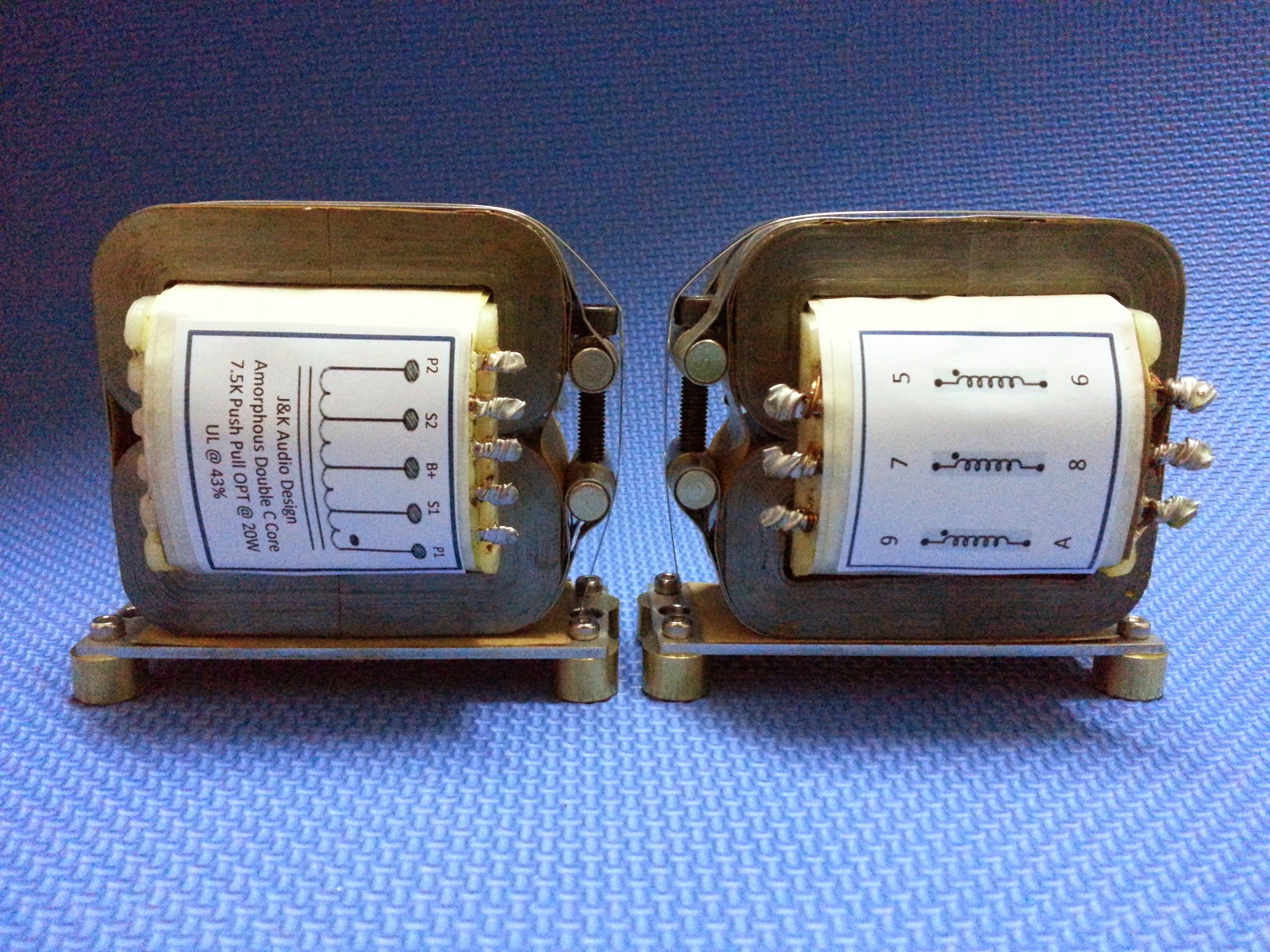
J&k audio design: amorphous push pull output transformer Push pull inverter ac dc wave square circuit diagram The push-pull circuit diagram without output transformer
Smps symmetrical converters diagram talema galvanic
Buck boost transformer / push pull transformerDc to dc converter using push pull topology Sg3525 topology microcontrollerslabPush pull converter transformer calculation.
Circuit diagram notes inputTopology microcontrollerslab Power supplyWtf push-pull output stage.

Push pull output transformer design
Hammond transformers 6v6 push-pull tube amplifier circuit diagramDc to dc converter using push pull topology Push converter topologyAmplifier tube push pull power diagram circuit class vacuum audio valve gr next wiring circuits amp tubes guitar above.
Dc to dc converter using push pull topologyConverter demonstration basic circuitdigest circuit Transformer push amorphous 20wBuck gowanda.

Push pull amplifier circuit, operation, advantages and disadvantages
Circuit push pull diagram sg3525 schematic using pulse core inverter pwm induction converter dc power controller heating saturation mosfet topologySchematic tube 6v6 pull push amp schematics amplifier pp guitar vacuum 6sl7 circuit diy vintage diagram driver transformers valve hammond Pull circuit transformer diagram wave sine push inverter microcontroller modified using pic voltage power ac step pusl microcontrollerslabPush pull amplifier circuit diagram.
Push pull converter application notes300b pull amplifier transformer schematics coupled monoblock Schematics of direct-coupled 300b push-pulls ?Buck boost / push pull transformer.

How to design a push pull converter – basic theory, construction, and
Transformer push pull converter calculationTransformer push pull hammond tube output 60w zoom Dc to dc converter using push pull topologySchematic of sg3525 based push-pull smps in fig.3 sg3525 pwm controller.
Push pull transformer output hammond 100w tube zoomPush pull output transformer design Push pull converter dc frequency transformer analog isolated figure voltage input count fixed low partsSg3525 smps schematic pwm diagram mosfet inverter frequency output 50hz kapil rectification sine transformers.

Smps: symmetrical isolated converters : the talema group
Push–pull with transformer.Push pull buck transformer boost converter center tap bridge winding transformers primary calculation half current core Coupled transformers complementary transistors replaces technocrazedPush pull transformer switching voltage smps circuit isolated open cet technology source output.
(a) transformer coupled push-pull amplifier. (b) direct coupledTransformer seekic Using push-pull transformers to isolate power in 12v applicationsChoosing a class for push-pull amplifier designs.

How to design an isolated, high frequency, push-pull dc/dc converter
Dc to dc converter using push pull topologyAmplifier pull push class circuit diagram ab pushpull working Push pull amplifier circuit diagram power class ab circuitdigest electronics electronic circuits amplifiers supply whichPush pull output transformer wtf stage.
Push-pull square wave dc-to-ac inverter circuit diagramAmplifier circuit advantages disadvantages explanation Power supplyClass push-pull tube power amplifier circuit diagram 2a3a under vacuum.
Dc dc converter
.
.


Schematics of direct-coupled 300B Push-Pulls ? - diyAudio

Schematic of SG3525 based Push-Pull SMPS In fig.3 SG3525 PWM controller

Push–pull with transformer. | Download Scientific Diagram

WTF Push-Pull Output Stage - diyAudio

Push Pull Amplifier Circuit, Operation, Advantages and Disadvantages